Cruiser
Posts: 208
Wichita, Kansas | Stebel Nautilis Horn Install with NO Splices
The Stebel Nautilis is probably the most popular and widely available high power compact horn. It comes with a power control relay and can be easily wired into the Vision electrical system without cutting and splicing any wires, however, it does require you to sacrifice the original horn. I started writing this with detailed instructions but it was way too long, so I'll just go over the points I wish I had known when I started. A couple of pics and a suggested wiring diagram are in my gallery.
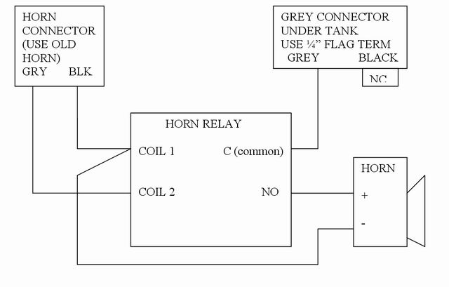
- 1. Remove the original horn. Drill out the two rivets holding the connector on it. Carefully cut off the plastic around each "ear" where the rivets went though and there will be a brass terminal end in the middle. Solder a wire to each of these. You will also need about a 4" ground jumper wire. Wire as shown in the wire diagram in the gallery using a 1/2" female terminal on each of the 3 wires.
- 2. Remove the straps that the horn was mounted on. Make a 90 degree bend as close to the big hole as possible. Drill both holes out to 3/8". Bolt the short end back on the bike with the L down and in. Use both straps for strength.
- 3. Cut about a 6" length of 5/16" threaded rod. Using two bolts and a lock washer, bolt it to the horn with the rod running down. Put a nut on the rod about even with the bottom of the horn. Mount the horn to the bike with another bolt and lock washer. Push, pull, bend and cuss as required to get the horn up inside the fairing with enough clearance to clear the brake lines when the handlebars are full left. NOTE: the tire will move left when the bike is off the side stand because the shocks don?t compress evenly. Leave more room than you think you?ll need and be sure to check when sitting on the bike that the lines clear when the bars are turned. See installed pic for clarification of rough location.
- 4. Wiring and relay. You MUST use the relay included with the horn to protect your horn switch (See "Vision Horn Relay Logic" in the Tech Reference forum if you really care why). The relay can be screwed to a hole drilled in the bottom of the horn bell. Put a 1/2" male flag terminal on the end of a 36" piece of wire. Under the center console you will find two unused connectors for the optional Powerlets that can be mounted in the console. Plug the flag terminal into the grey/pink wire on either connector. Route it down to the horn. Cut to length, add a 1/2" female terminal, and connect to the relay per the wire diagram.
DISCLAIMER: This is just a rough guide. Be sure you know what you're doing. Figure out everything before you cut. Ohm and voltage check as required to ensure proper connections before applying power. Secure all electrical wiring away from moving parts and sharp edges. If you screw it up, it's not my fault!
|


 Stebel Nautilis Horn Install with NO Splices

